Input Devices Convert Data Signals Into Continuous Electronic Waves or Pulses
Analog Signals vs. Digital Signals
DOWNLOAD PDF

Get valuable resources straight to your inbox - sent out once per month
We value your privacy
A signal is an electromagnetic or electrical current that carries data from one system or network to another. In electronics, a signal is often a time-varying voltage that is also an electromagnetic wave carrying information, though it can take on other forms, such as current. There are two main types of signals used in electronics: analog and digital signals. This article discusses the corresponding characteristics, uses, advantages and disadvantages, and typical applications of analog vs. digital signals.
Analog Signal
An analog signal is time-varying and generally bound to a range (e.g. +12V to -12V), but there is an infinite number of values within that continuous range. An analog signal uses a given property of the medium to convey the signal's information, such as electricity moving through a wire. In an electrical signal, the voltage, current, or frequency of the signal may be varied to represent the information. Analog signals are often calculated responses to changes in light, sound, temperature, position, pressure, or other physical phenomena.
When plotted on a voltage vs. time graph, an analog signal should produce a smooth and continuous curve. There should not be any discrete value changes (see Figure 1).
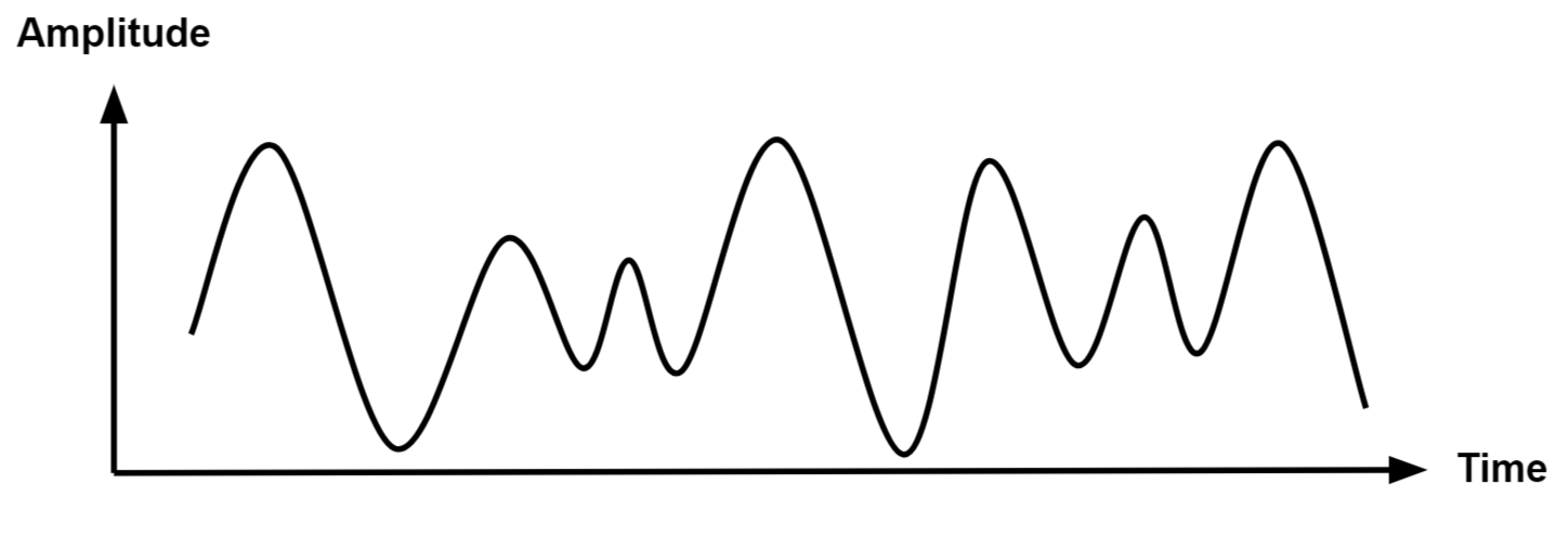
Figure 1: Analog Signal
Digital Signal
A digital signal is a signal that represents data as a sequence of discrete values. A digital signal can only take on one value from a finite set of possible values at a given time. With digital signals, the physical quantity representing the information can be many things:
- Variable electric current or voltage
- Phase or polarization of an electromagnetic field
- Acoustic pressure
- The magnetization of a magnetic storage media
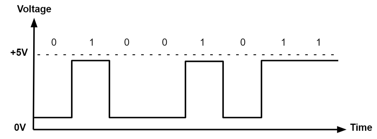
Digital signals are used in all digital electronics, including computing equipment and data transmission devices. When plotted on a voltage vs. time graph, digital signals are one of two values, and are usually between 0V and VCC (usually 1.8V, 3.3V, or 5V) (see Figure 2).
Analog Electronics
Most of the fundamental electronic components — resistors, capacitors, inductors, diodes, transistors, and operational amplifiers (op amps) — are all inherently analog components. Circuits built with a combination of these components are analog circuits (see Figure 3).
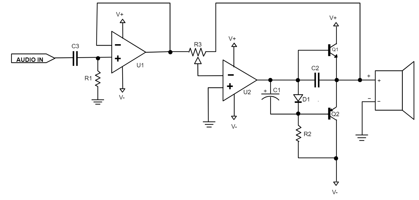
Figure 3: Analog Circuit
Analog circuits can be complex designs with multiple components, or they can be simple, such as two resistors that form a voltage divider. In general, analog circuits are more difficult to design than digital circuits that accomplish the same task. It would take a designer who is familiar with analog circuits to design an analog radio receiver, or an analog battery charger, since digital components have been adopted to simplify those designs.
Analog circuits are usually more susceptible to noise, with "noise" being any small, undesired variations in voltage. Small changes in the voltage level of an analog signal can produce significant errors when being processed.
Analog signals are commonly used in communication systems that convey voice, data, image, signal, or video information using a continuous signal. There are two basic kinds of analog transmission, which are both based on how they adapt data to combine an input signal with a carrier signal. The two techniques are amplitude modulation and frequency modulation. Amplitude modulation (AM) adjusts the amplitude of the carrier signal. Frequency modulation (FM) adjusts the frequency of the carrier signal. Analog transmission may be achieved via many methods:
- Through a twisted pair or coaxial cable
- Through an optical fiber cable
- Through radio
- Through water
Much like the human body uses eyes and ears to capture sensory information, analog circuits use these methodologies to interface with the real world, and to accurately capture and process these signals in electronics.
MPS makes a variety of analog ICs and components, such as the MP2322, a low IQ synchronous step-down converter in a tiny 1.5mmx2mm QFN package.
Digital Electronics
Digital circuits implement components such as logic gates or more complex digital ICs. Such ICs are represented by rectangles with pins extending from them (see Figure 4).
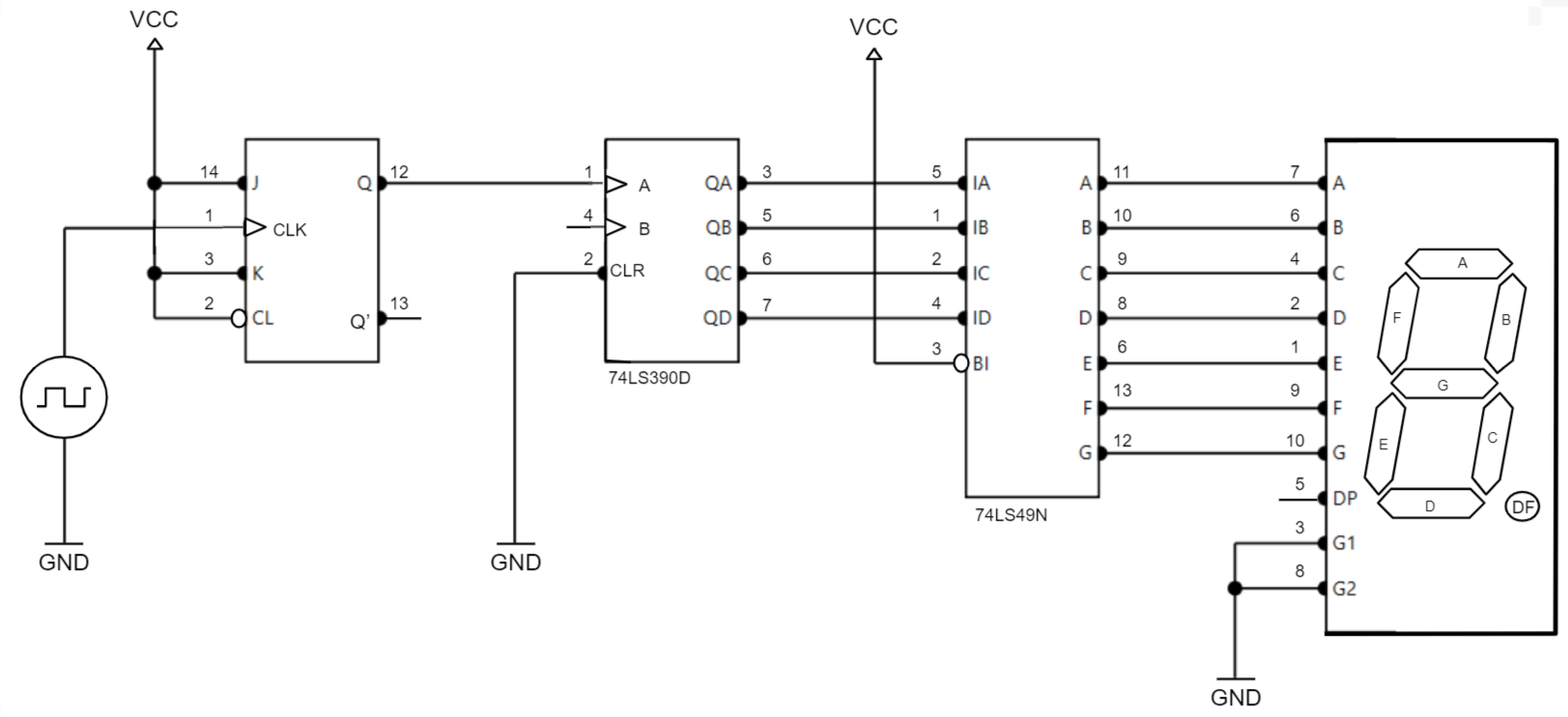
Figure 4: Digital Circuit
Digital circuits commonly use a binary scheme. Although data values are represented by just two states (0s and 1s), larger values can be represented by groups of binary bits. For example, in a 1-bit system, a 0 represents a data value of 0, and a 1 represents a data value of 1. However, in a 2-bit system, a 00 represents a 0, a 01 represents a 1, a 10 represents a 2, and a 11 represents a 3. In a 16-bit system, the largest number that can be represented is 216, or 65,536. These groups of bits can be captured either as a sequence of successive bits or a parallel bus. This allows large streams of data to be processed easily.
Unlike analog circuits, most useful digital circuits are synchronous, meaning there is a reference clock to coordinate the operation of the circuit blocks, so they operate in a predictable manner. Analog electronics operate asynchronously, meaning they process the signal as it arrives at the input.
Most digital circuits use a digital processor to manipulate the data. This can be in the form of a simple microcontroller (MCU) or a more complex digital signal processor (DSP), which can filter and manipulate large streams of data such as video.
Digital signals are commonly used in communication systems where digital transmission can transfer data over point-to-point or point-to-multipoint transmission channels, such as copper wires, optical fibers, wireless communication media, storage media, or computer buses. The transferrable data is represented as an electromagnetic signal, such as a microwave, radio wave, electrical voltage, or infrared signal.
In general, digital circuits are easier to design, but they often cost more than analog circuits that are intended for the same tasks.
MPS's catalog of digital components includes the MP2886A, a digital multi-phase PWM controller with a PWM-VID interface compatible with NVIDIA's Open VReg specification.
Analog-to-Digital (ADC) and Digital-to-Analog (DAC) Signal Conversion
Many systems must process both analog and digital signals. It is common in many communications systems to use an analog signal, which acts as an interface for the transmission medium to transmit and receive information. These analog signals are converted to digital signals, which filter, process, and store the information.
Figure 5 shows a common architecture in which the RF analog front-end (AFE) consists of all analog blocks to amplify, filter, and gain the analog signal. Meanwhile, the digital signal processor (DSP) section filters and processes the information. To convert signals from the analog subsystem to the digital subsystem in the receive path (RX), an analog-to-digital converter (ADC) is used. To convert signals from the digital subsystem to the analog subsystem in the transmit path (TX), a digital-to-analog converter (DAC) is used.
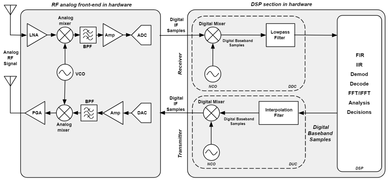 Figure 5: Communication System with Analog and Digital Subsystems
A digital signal processor (DSP) is a specialized microprocessor chip that performs digital signal processing operations. DSPs are fabricated on MOSFET integrated circuit chips, and are widely used in audio signal processing, telecommunications, digital image processing, high-definition television products, common consumer electronic devices such as mobile phones, and in many other significant applications.
A DSP is used to measure, filter, or compress continuous real-world analog signals. Dedicated DSPs often have higher power efficiency, making them suitable in portable devices due to their power consumption constraints. A majority of general-purpose microprocessors are also able to execute digital signal processing algorithms.
ADC Operation
Figure 6shows ADC operation. The input is the analog signal, which is processed through a sample-hold (S/H) circuit to create an approximated digital representation of the signal. The amplitude no longer has infinite values, and has been "quantized" to discrete values, depending on the resolution of the ADC. An ADC with a higher resolution will have finer step sizes, and will more accurately represent the input analog signal. The last stage of the ADC encodes the digitized signal into a binary stream of bits that represents the amplitude of the analog signal. The digital output can now be processed in the digital domain.
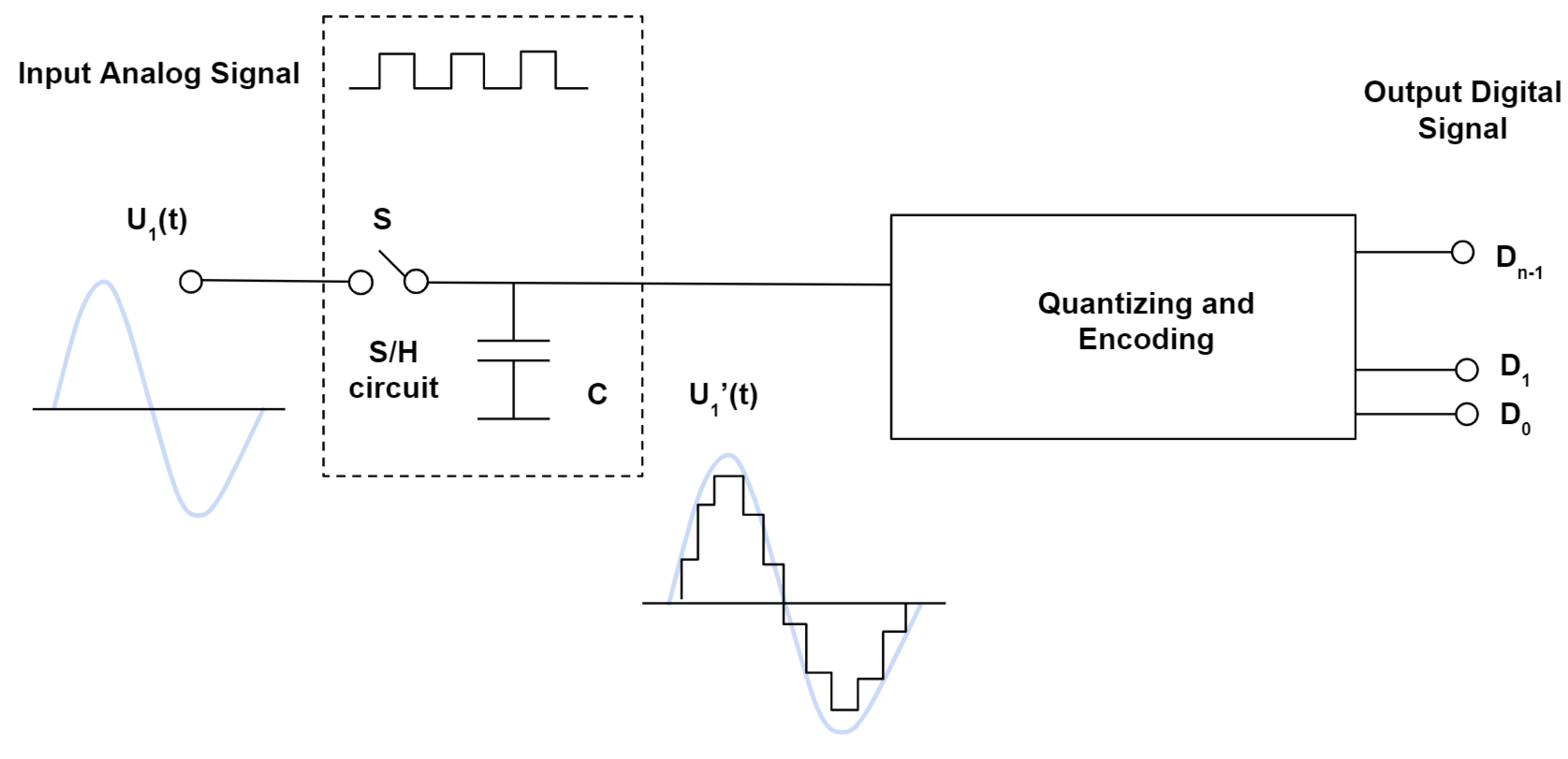
Figure 6: Typical ADC Architecture for Analog to Digital Signal Conversion
DAC Operation
A DAC provides the reverse operation. The DAC input is a binary stream of data from the digital subsystem, and it outputs a discrete value, which is approximated as an analog signal. As the resolution of the DAC increases, the output signal more closely approximates a true smooth and continuous analog signal (see Figure 7). There is usually a post filter in the analog signal chain to further smooth out the waveform.
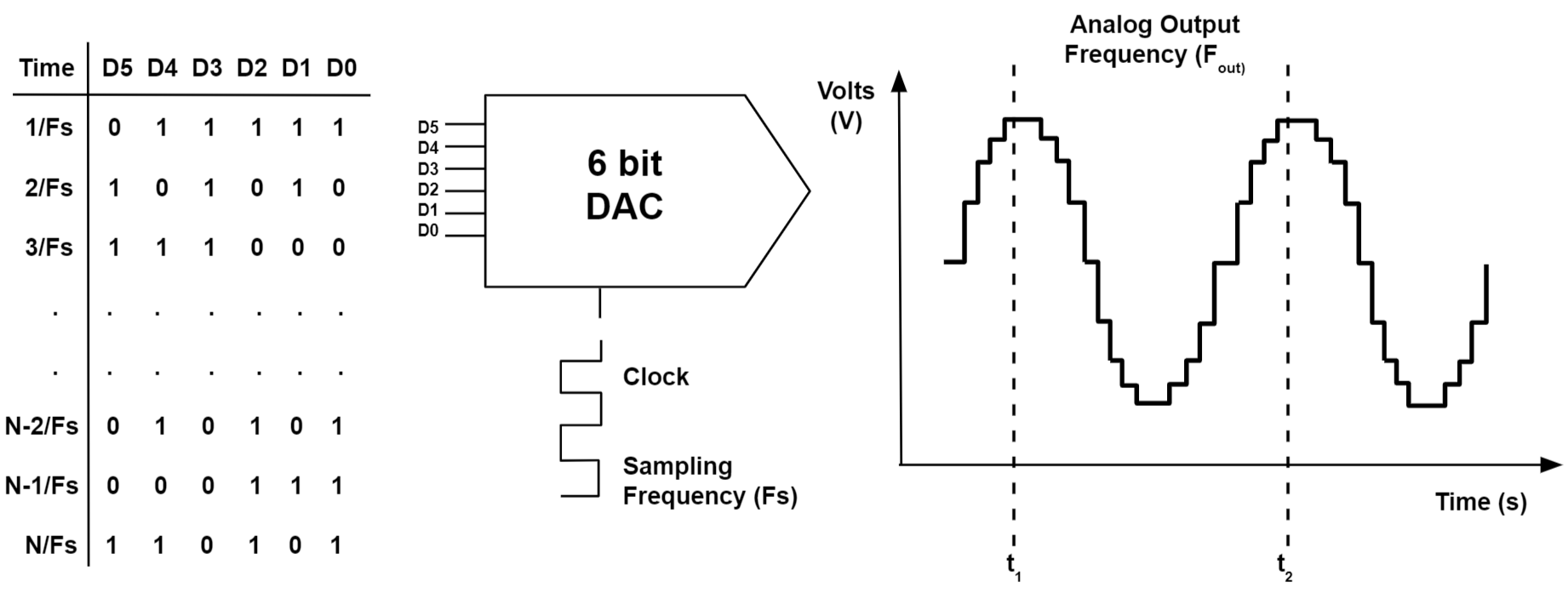
Figure 7: 6-Bit DAC for Digital-to-Analog Signal Conversion
As mentioned before, many systems used today are "mixed signal," meaning they rely on both analog and digital subsystems. These solutions require ADCs and DACs to convert information between the two domains.
Digital Signals vs. Analog Signals: Advantages and Disadvantages
As with most engineering topics, there are pros and cons for both analog and digital signals. The specific application, performance requirements, transmission medium, and operating environment can determine whether analog or digital signaling (or a combination) should be used.
Digital Signals: Advantages and Disadvantages
Advantages to using digital signals, including digital signal processing (DSP) and communication systems, include the following:
- Digital signals can convey information with less noise, distortion, and interference.
- Digital circuits can be reproduced easily in mass quantities at comparatively low costs.
- Digital signal processing is more flexible because DSP operations can be altered using digitally programmable systems.
- Digital signal processing is more secure because digital information can be easily encrypted and compressed.
- Digital systems are more accurate, and the probability of error occurrence can be reduced by employing error detection and correction codes.
- Digital signals can be easily stored on any magnetic media or optical media using semiconductor chips.
- Digital signals can be transmitted over long distances.
Disadvantages to using digital signals, including digital signal processing (DSP) and communication systems, include the following:
- A higher bandwidth is required for digital communication when compared to analog transmission of the same information.
- DSP processes the signal at high speeds, and comprises more top internal hardware resources. This results in higher power dissipation compared to analog signal processing, which includes passive components that consume less energy.
- Digital systems and processing are typically more complex.
Analog Signals: Advantages and Disadvantages
Advantages to using analog signals, including analog signal processing (ASP) and communication systems, include the following:
- Analog signals are easier to process.
- Analog signals best suited for audio and video transmission.
- Analog signals are much higher density, and can present more refined information.
- Analog signals use less bandwidth than digital signals.
- Analog signals provide a more accurate representation of changes in physical phenomena, such as sound, light, temperature, position, or pressure.
- Analog communication systems are less sensitive in terms of electrical tolerance.
Disadvantages to using analog signals, including analog signal processing (ASP) and communication systems, include the following:
- Data transmission at long distances may result in undesirable signal disturbances.
- Analog signals are prone to generation loss.
- Analog signals are subject to noise and distortion, as opposed to digital signals which have much higher immunity.
- Analog signals are generally lower quality signals than digital signals.
Analog and Digital Signals: Systems and Applications
Traditional audio and communication systems used analog signals. However, with advances in silicon process technologies, digital signal processing capabilities, encoding algorithms, and encryption requirements — in addition to increases in bandwidth efficiencies — many of these systems have become digital. They are still some applications where analog signals have legacy use or benefits. Most systems that interface to real-world signals (such as sound, light, temperature, and pressure) use an analog interface to capture or transmit the information. A few analog signal applications are listed below:
- Audio recording and reproduction
- Temperature sensors
- Image sensors
- Radio signals
- Telephones
- Control systems
MPS has a broad portfolio of analog parts, including the MP2322, MP8714, MP2145, and MP8712.
Although many original communication systems used analog signaling (telephones), recent technologies use digital signals because of their advantages with noise immunity, encryption, bandwidth efficiency, and the ability to use repeaters for long-distance transmission. A few digital signal applications are listed below:
- Communication systems (broadband, cellular)
- Networking and data communications
- Digital interfaces for programmability
Visit our website to learn more about MPS's digital parts, such as the MP2886A, MP8847, MP8868, MP8869S, and MP5416.
Conclusion
This article introduces some of the basic concepts of analog and digital signals, and their uses in electronics. There are clear advantages and disadvantages with each technology, and knowing your application's needs and performance requirements will help you determine which signal(s) to choose.
_________________________
Did you find this interesting?Get valuable resources straight to your inbox - sent out once per month!
Related Forum Topics
Get technical support
Source: https://www.monolithicpower.com/en/analog-vs-digital-signal
0 Response to "Input Devices Convert Data Signals Into Continuous Electronic Waves or Pulses"
Post a Comment