Cryoem Grids Continuous Film Overlay Carbon Product
Sample behavior on cryoEM grids
Sample behavior on cryoEM grids
PreviewLesson summary:
What happens to samples when they are added to grids and frozen? In this lesson, we will explore critical aspects of cryoEM grid preparation, known effects on samples, and common hurdles that must be overcome during sample screening and grid optimization.
Lesson concepts:
- How air/water and water/surface interfaces strongly affect sample behavior on grids
- How grid supports, grid substrates, and ice thickness affect sample behavior
Online educational resources:
- cryoEM101.org: Chapter 2 – CryoEM Grid Preparation
- EM-Learning.com: CryoEM / Learning / Getting Started in CryoEM / Part 5 – Sample Prep: Grids
- EM-Learning.com: CryoEM / Learning / Getting Started in CryoEM / Part 7 – SPA Sample Prep
Workshops & presentations
- SEMC 2020 CryoEM Short Course (January 2020)
- MRC-LMB 2017 CryoEM Course: Sample preparation – Lori Passmore
- NRAMM/SEMC CryoEM Grid Preparation Workshop (May 2017)
Introduction to cryoEM sample preparation
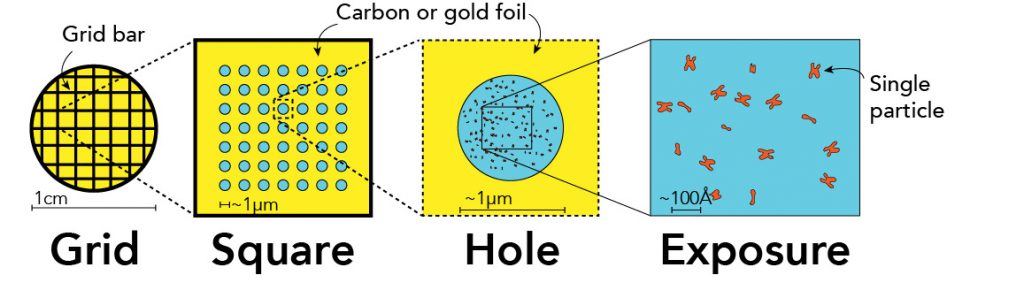
EM grids are ~3mm in diameter and are typically nanofabricated to have regularly spaced patterns – a mesh pattern on which is suspended a thin foil (i.e., carbon or gold) with a regular array of micrometer-sized holes – that not only provides structural rigidity but can also be used for automated data acquisition. EM samples are directly applied to the prepared surface of the grids whereby an excess solution is removed to leave a thin film of solution suspended across the open holes in the foil, typically 0.5 – 2 µm in diameter.
Ultimately, within the holes are cryoEM specimens for either single particle or cryoET data collection. An example of which is shown here:
To see other examples of what it looks like to visualize cryoEM grids across different orders of magnitude:
Dr. Janet Iwasa's 3D rendered zoom & narration (via cryoEM101.org):
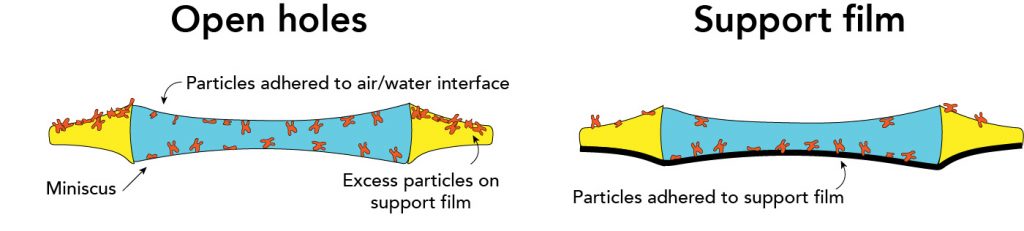
To understand sample behavior, it is useful to consider a 'side-on' view of single particles within a hole. When considered in this direction, we are looking at a slice through a hole to show a cross-section of a cryoEM sample. In general, there are two types of approaches to prepare cryoEM grids: 'open holes' vs. 'support film'. In the open hole approach, the sample is incubated with grids at high concentrations so that the sample 'spills over' into the holes. As an orthogonal approach, support films can be added on top of the holes to allow samples to adhere directly to the support.
Grid preparation
Before discussing the details of open-hole vs. support film grids it is important to have a basic understanding of how cryoEM grids are prepared for the sample application. To facilitate automated data collection, cryoEM grids can be purchase from vendors or prepared in-house (e.g. Marr et al. 2014). Once obtained, cryoEM grids are typically hydrophobic, which means that they will resist wetting by your sample + buffer. To ensure sample adherence, grids are made more hydrophilic by exposing them to plasma through glow-discharging or plasma cleaning. While similar, glow-discharging and plasma cleaning utilize distinct approaches.
- Glow discharging creates a plasma from air to modify grid surfaces
- Plasma cleaning refers to a different device that specifically makes a plasma for surface modification. Plasma cleaning uses gas mixtures (e.g. Argon:Oxygen) to impart specific effects.
Support film grids are prepared using glow discharging or specific plasma. For amorphous carbon, glow charging or plasma cleaning is appropriate, whereas grids that have graphene require plasma such as hydrogen gas.
Grid types
Open holes
Key concepts:
-
-
- Samples adhere to the air/water interface within open holes
- Need to add a high concentration of sample so that the support film becomes saturated, allowing samples to spill over into holes
-
Practical considerations:
-
- Benefits:
- High contrast of single particles given that there is no additional layer
- Predominant approach for cryoEM grid preparation
- 'Only' need to add the sample to the grid after the grid is prepared using glow discharging or plasma cleaning.
- Drawbacks:
- Relatively high sample concentration is added to grids (typically ~1 mg/mL) to get samples into holes
- The air/water interface exerts inconsistent effects onto cryoEM samples (i.e. different samples experience the air/water interface differently)
- Benefits:
Support film
Key concepts:
-
- Samples adhere to directly to a support film that is made from amorphous carbon, graphene, or graphene oxide, keeping samples away from air/water interface.
- Less sample is required that open holes (typically 10X less), comparable to the concentration used for negative stain, which is 0.1 mg/mL.
Practical considerations:
-
- Benefits:
- Samples are adhered to support film and kept away from air/water interface.
- Drawbacks:
- Have to prepare film in-house. Requires hands-on training and practice to prepare reproducible films
- Specific plasma cleaning or glow discharging machines are required to make the surface appropriately hydrophilic
- The thickness of the amorphous carbon support film will decrease the contrast of the images. Graphene and graphene oxide grids should be optically transparent in the beam.
- Benefits:
Source: https://cryoedu.org/lesson/sample-behavior-on-cryoem-grids/
0 Response to "Cryoem Grids Continuous Film Overlay Carbon Product"
Post a Comment